Photogrammetry 101
Photogrammetry 101
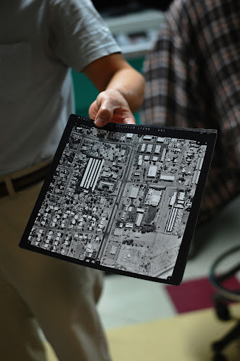
An example of an aerial photograph.
When it comes to designing a road, just knowing where it’s going to be built isn’t enough – engineers have to really understand the area’s features and terrain before they can even begin to plan.
This is where ADOT’s Engineering Survey section comes in…
It is responsible for conducting field surveys, CAD operations and aerial photography. The section also is in charge of photogrammetry and mapping, which is what we’re blogging about today (but, we promise we’ll cover that other stuff soon).
What is photogrammetry?
Photogrammetry is the science of making precise measurements utilizing aerial photographs to make accurate maps, surveys and Orthophotos.
In other words, photogrammetrists, with the help of computer software, can use a pair of aerial photos (called a stereomodel) and turn it into a useful map capable of showing engineers what the surface of a particular piece of land looks like.
Not only do these maps indicate where things like existing roads, signs, wells, power poles, manholes, fences and cattle guards are, but because they provide so much information the maps can also help engineers calculate how much dirt is going to be needed or moved to build the road.
It all starts with aerial photographs. The photos are taken with a 60-65 percent overlap so photogrammetrists (again with the help of computer software and special 3D glasses) can see a three-dimensional view of the ground. From there they use a specially designed computer mouse (also known as a stealth mouse) to collect all features and draw breaklines (three-dimensional lines used to collect points) that indicate where there’s a change in terrain elevation.
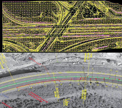
The generation of a DTM (top) and an Orthophoto.
Final result
Depending on the need of any particular project, the ADOT photogrammetry section can create several types of products:
- Digital Terrain Models (DTM), which show a three-dimensional view of what the surface of the ground looks like. A DTM is used to create an Orthophoto and calculate quantities. It is also used for environmental needs and up and down stream for rivers and washes for the construction of bridges.
- Planimetric maps, which are also known as line maps. They indicate the exact position of the features on the ground. They can also show contours that display what the ground surface represents.
- Orthophotos, which are enlarged photographs of an area that have been corrected to show accurate scale.
More on photogrammetry can be found on the ADOT website.